|
|
|
Event structure: native ATM

|
Event Structure |
What is an ATM event ?... |
 |
|
native ATM display |
by using Clarinet Event-Editor without
any filter ... |
|
|
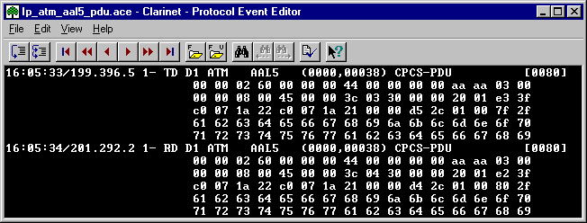
ATM decoding |
by using Clarinet Event-Editor with a
filter ... |
 |
|
Standards |
|
|
ATM event
The ATM events are generated by the analysis process from the SL or DL link
with the Cell or CPCS-PDU acquisition mode.
The binary event structure is defined in the Clarinet-API.

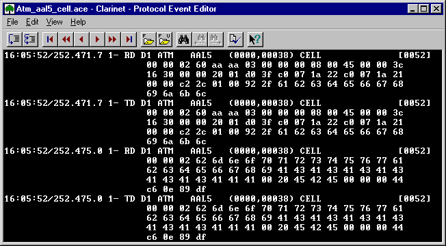
Clarinet Event-Editor: native ATM display
The edition of the ATM events without any decoding/formatting allows to
display the content of the differents fields according to the Cell or CPCS-PDU
acquisition mode:
|
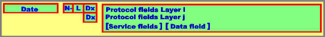
Event information |
Date |
Date of the event (end of cell or PDU) in
the format: hh:mm:ss/xxx.yyy.z |
|
| N |
The interface number which identifies the
Clarinet-interface connected to the host. |
| Link type |
- TS: Signalling Link Transmit
direction
- RS: Signalling Link Receive
direction
- TD: Data Link Transmit
direction
- RD: Data Link Receive
direction
|
| D1 |
The decoding level as specified in the
filter (protocol stack). |
|
Protocol fields |
ATM |
<AAL type> Ctrl <ATM
type> [nnnn] |
|
|
Content |
displayed in hexadecimal.
- for Cell, header and information fields.
- for CPCS-PDU, Cell header, conveyed data, and other fields.
|
|
|
<AAL type> |
|
|
Ctrl |
Control field in the format (xxxx,yyyy)
: |
| |
xxxx |
decimal value of VPI within the cell
header. |
| |
yyyyy |
decimal value of VCI within the cell
header. |
|
<ATM_type> |
|
|
[nnnn] |
The number of octets included in the Cell
or CPCS-PDU content. |
|
