| |
|
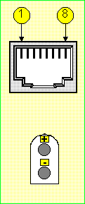
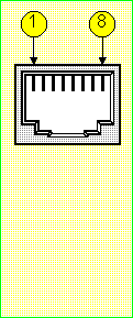
ISDN BRI (U) - Interface signals
 |
|
Pin
1
2
3
4
5
6
7
8
|
Signal
NC
NC
NC
U interface (PW1+)
U interface (PW1-)
NC
NC
NC
(NC = not connected) |
Signal
NC
NC
NC
U interface (PW1+)
U interface (PW1-)
NC
NC
NC
(NC = not connected) |
Pin
1
2
3
4
5
6
7
8 |
|
 |
Clarinet Book SCSI type
|
Clarinet Book USB type
|
Characteristics
|
Standards |
Functional
& electrical
|
G961 for operation in analysis or NT, LT simulation.
A POWER (or PWR IN) 2-pin connector enables the use
of an auxiliary Power-adapter unit for the Clarinet interface to
supply the PW1 signal when the selected operation is LT
simulation. |
Mechanical
|
2x ISO-8877 8-pin RJ45 connectors. |
The two RJ45 connectors can be used for operation in analysis or simulation.
ISDN Mode
|
Connexion |
Monitoring
|
Connection uses the serial mode with both connectors :
- FROM LT (from line termination, ie network side)
- FROM NT (from network termination, ie user side)
|
User Simulation
|
|
Network Simulation
|
|
|

