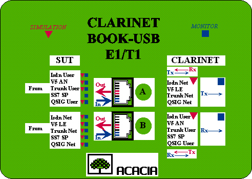
How to connect E1/T1 interface to Clarinet USB PRI

Rules of wiring

e1t1_ph_con01.jpg (9933 octets) The interface between the "User" and the "Network" over an E1/T1 interface is defined for two pair signals :
  • T: Transmit direction
  • R: Receive direction

Both directions refer to the User side. Pin allocation is defined over the RJ45 connector.

e1t1_ph_con00.jpg (154129 octets)

The label at the top of the Clarinet-Book E1/T1 displays wiring and logical functions:

  • A and B ports are used for monitoring or simulation.

  • monitoring uses simultaneously the both A and B ports: each of them monitors one direction

  • simulation uses either one A or B port

All  signals acting as an Input are displayed in Blue.
All signals acting as an Output are displayed in Red.

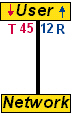
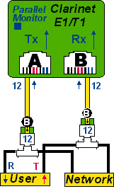
Monitoring in parallel mode - RJ45

e1t1_ph_con02.jpg (55289 octets)

The User-Network link is splitted :

  • Original Network-User  cable  is connected to the splitter from the Network side

  • A regular RJ45 straight cable is added from the User to the splitter

  • The "C"  RJ45 straight cable connects the both splitters

  • The "B" straight 12-12 cable extract the Rx signal

  • The "A" crossed 45-12 cable extract the Tx signal

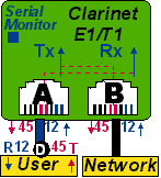
The profile must use 'High-impedance" input.

Monitoring in serial mode - RJ45

e1t1_ph_con03.jpg (33702 octets)

The User-Network link is splitted :

  • Original Network-User  cable  is connected from the Network to the B port

  • The "D" crossed 1245-4512 cable is added from the User to the A port

The profile must use '120 / 100 / 75 Ohms " inputs.

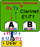
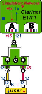
Network simulation - RJ45

e1t1_ph_con05.jpg (25721 octets)

The E1/T1 link is connected as an extremity :

  • "D" crossed 1245-4512 cable is connected from the User to the A port

The profile must use '120 / 100 / 75 Ohms " inputs.

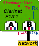
User simulation - RJ45

e1t1_ph_con04.jpg (25721 octets)

The E1/T1 link is connected as an extremity :

  • Regular Network-User  cable  is connected from the Network to the B port

The profile must use '120 / 100 / 75 Ohms " inputs.

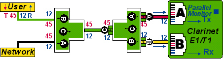
Parrallel monitoring - BNC

e1t1_ph_con06.jpg (37738 octets)

The both BNC cables are splitted  with a T connector:

  • The "B" straight 12-12 cable connected through a BNC-RJ45 adapter extracts the Rx signal

  • The "B" straight 12-12 cable connected through a BNC-RJ45 adapter extract the Tx signal

The profile must use 'High impedance " inputs.

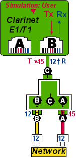
User simulation - BNC

e1t1_ph_con07.jpg (40540 octets)

The E1/T1 link is connected as an extremity on port B:

  • The "C"  RJ45 straight cable connects to the RJ45 splitter

  • The "B" straight 12-12 cable   is connected to the RJ45-BNC adapter to carry Rx signal

  • The "A" crossed 45-12 cable   is connected to the RJ45-BNC adapter to carry Tx signal

The profile must use '120 / 100 / 75 Ohms " inputs.

Network simulation - BNC

e1t1_ph_con08.jpg (41466 octets)

The E1/T1 link is connected as an extremity on port A:

  • The "C"  RJ45 straight cable connects to the RJ45 splitter

  • The "B" straight 12-12 cable   is connected to the RJ45-BNC adapter to carry Rx signal

  • The "A" crossed 45-12 cable   is connected to the RJ45-BNC adapter to carry Tx signal

The profile must use '120 / 100 / 75 Ohms " inputs.


home     Quick start     Specifications     Connections     Features     How to?     Notes     Search     Site Map

updated:  27-Feb-04